 home coil info products ordering
Loohan Communications Office
Orgone Technical Bulletin # 25
September, 2007
Electronic Amplification
formerly entitled "Ultrasound Amplification"
Ultrasound amplification of psionic signals, be they from hand/head pickup devices (more on that later), dial boxes, or robocops (or really any programmed crystal/orgone type of device) is one of the major power boosts I have come across yet. Much better than acoustic-range audio amps. I mentioned this in my blog on July 13:
Ultrasound: A while back my Santa Rosa friend sent me a couple slightly used Flanagan Neurophones, thinking i might be able to reverse the function in the DSP and use it as a psi-amp. Indeed, i was able to pipe in 2 inputs, which it amped into a stereo ultrasound output. Running this into mobius devices seemed to drain the battery real quickly (though, it may have been a failing battery that made it seem like that) so i developed a superior
itter to plug into the output. The simple little transmitter is extremely powerful with ultrasound input, and moreover has imbedded copper screen as a passive pickup with a lead soldered to it so i can run the signal into all my other stuff.
This is tremendously powerful, but since i am off-grid, i have to charge the battery at work, and have limited time usage at home. Moreover, it eats expensive batteries at an unbelievable rate. I just replaced the battery pack for $27 and it failed after a few uses. This is not due to draw.
Let me back up a little. I have an older DSP that does not have the golden ratio output, but that's OK since it probably wouldn't affect the output from an outside source (my rad box and RoboCop) anyway. I also have this little jobber that does have golden-ratio output, but does not accept outside input. Recently i built an even better transmitter that takes in the outputs from both NPs simultaneously. By running them both, psionic power is 5X what it is on the DSP alone. The little one runs on 2 AAA cells for hours on the transmitter, so it's not something wrong with my usage causing the DSP's problems. I think something is wrong with the charging electronics, as no matter how long you leave it plugged in, the adapter and DSP remain pretty warm, even though it is allegedly overcharge-protected.
But the real reason i'm typing all this is an appeal for help in the form of information. Does anyone have a grasp of ultrasound electronics? Ultrasound is sound above 20K Hz basically, and i'm wondering if a common mono amp can be modified to take in a radionics signal and output ultrasound, with volume control. (And that's another point: the DSP kicks the hardest with the gain turned way down, almost off.)
The transmitters are very easy to make, but i will not release the info on these unless an affordable amp system is found, so that others at a grass-roots level can use this tech, too. Otherwise, it would be mainly the NSA and CIA copying my transmitter.
Apparently the Neurophone DSP has some charging problems, so I bypassed the battery/charger and pipe in 12V DC from another stabilized source, which seems to work fine. I have been using it for weeks non-stop, and it runs cool even in hot weather.
But it is not necessary or recommended to invest in these pricey devices.
Because it turns out my friend Sittingtaoist is an old electronics geek, and he came to the rescue with a cheap alternative. In fact you might want to stop right now and purchase a couple or more Velleman K1803 pre-amp kits. Also you will need a chip to replace the (inadequate) one in each kit. You may be able to order them through Radio Shack; it's a NE5534 chip. You will also need a 10 kOhm 1/4 watt resistor for each kit.
Note: Sittingtaoist thinks the Velleman K2572 kit, which is a stereo pre-amp might work well, too, even with the native chip, and that way you get 2 outputs for less than the price of 2 K1803s. Intuitively, I think it would work well, too. But neither of us has tested it yet. At the source linked above, you can get this kit for twice the price of a K1803, but you save the cost of 2 chips (hopefully). I will probably be getting a couple of these kits in a few weeks.
The Transmitter: As mentioned in the last OTB, there are such things as "ultrasound transducers" but although they may broadcast ultrasound, they do not transmit any psionic aspects or subtle-energy well. I devised a water-based transmitter. I have no idea if it transmits ultrasound, but it does transmit the psionic signal that is amplified by an ultrasound amplifier.
You can experiment, if you like, with piping the output directly into mobius devices. My impression was that this creates a load demand, sucking more juice and probably shortening the life-span of the electronics. But I am an electronics dunce with limited experience. I only tested this with the DSL when it was having charging problems.
In any case, the transmitter I came up with is very easy to make, and seems much more powerful than piping the output directly into the coil/orgone array.
 Here is the first unit I made, with 2 small bottles of the hypodermic medicine variety (though 1/2 or 1 oz glass bottles, e.g. cobalt blue screw-top bottles, should work just as well). Size does not seem to matter per se, but small is better because one can get better resonant spacing.
Drill a small hole in the top of each and poke a wire (maybe 22-24 awg) through the top, after stripping some insulation from the tip. Warning: I once tried using braided wire for this, and water actually wicked through it and dripped out the cut end outside! Use solid wire.
Then thread the wire through a small gem bead (some are better than others). I used howlite beads in my 1st unit. They were dyed blue, but that doesn't hurt the energy. (In the 2nd unit I used tiny garnet beads, as the bottlenecks were too small for the howlite.) Any quartz, topaz would also do. I also put 3 tiny spiral sea shells in each bottle (nice if you happen to have some). Then 1/2-fill each bottle with charged water.
The bottles are basically it! You don't even need to pour any resin. I used bottles for a while by themselves, with the 2 outputs from the DSL feeding into the bottles, and it was phenomenally powerful with the bottles just setting on the countertop. Spacing is key for optimum resonance. Exactly 2" on center was optimum for this 2-bottle unit. This is why I recommend at least 2 bottles, even if you only have 1 mono pre-amp. One bottle will work, but will only be maybe 1/5 as strong as 2 bottles
driven from one amplifier. (Normally; but further down you will read about a good 1-bottle transmitter.) And if you have 2 different ultrasound amplifiers each running one of the bottles, it
might be many times more powerful.
However, having 2 bottles sitting around is a bit awkward, as they tend to fall over when you pull on the wires, etc. and it's hard to maintain proper spacing. So I cast the bottles in clear epoxy with a copper screen soldered to an output wire. An aluminum window screen scrap (hardware stores give old scraps away) would also work fine, or a mobius coil. The purpose of this is to passively pick up the vibe so you can pipe it into other orgone transmitters.
I just recently assembled my first K1803, so right now I have it driving both of the bottles of my 1st unit. But I dowse that if I had 2 K1803s, one for each bottle, it would be 3X as strong. What about more? 3 bottles is little or no better, if in a row, but in a triangular configuration with optimum spacing might be a different story. 4 bottles/pre-amps in a row would be 3X as strong as 2. So 4 bottles/pre-amps would be about 9X as strong as 1 pre-amp driving 2 bottles. Also, just as good as my $750 worth of Neurophones. Well, maybe not quite, because the golden ratio output of the GRS is, I think, superior as a synergist.
Of course, each pre-amp would be amplifying a different input. Some of these could be simple trends on a dial box, such as a particular freq expressed in Hz, or a sacred symbol.
More than 4? I doubt you would get much better results in a single module, but you could make more than one module if you were an unreasonable person. This is much more cost-effective than buying a GRS. One could even make 2 or more modules of 4 bottles each and pour a thinnish layer of resin in a rectangular tray, then set the modules in the resin in rows with proper spacing between them.
Here's a pic of an early stage of my second ultrasound transmitter, so you can get the idea:
 The spacing is different on 4. On my 4-banger, I used really tiny bottles (you can tell by the pic; that's 22 awg phone wire coming out of the bottles).
Assembling the K1803 kit: This is not for everyone. It is a very simple little kit, but requires a soldering iron with a fine tip, and a magnifying glass. I didn't have a suitable iron handy, so I put it together with Wire Glue (cheaper from other retailers). This is a useful product for some things (e.g.if you want to solder wire onto aluminum screen), but I probably won't use it for circuit boards in the future. A few considerations:The consistency of the product is such that if you attempt to put a small blob on the circuit board, it either will be too small a blob to have enough gravity to drip off your toothpick, or so large it slops over onto adjoining conductive surface. I'm exaggerating slightly, but I did spend some time scraping off excess goo and re-doing joints where the goo seemed to avoid the junction in favor of its surroundings.Anything coated with the stuff repels solder, should you attempt to re-do it with solder.Heat from a soldering gun will break the connection. For this reason, I had to re-glue all the posts that I soldered leads to, as soldering one end of the post loosens the other.The breaking strength of this product is a tiny fraction of that of solder.
Nonetheless, it is a feasible alternative that works, for those not into soldering.
Just as Jon Goldman recommends not using the ground posts (except for the electrical input one) in the acoustic amp, I did likewise with this unit. So just the + lead in, and the + lead out. You couldn't drive the transmitters I designed from the 2 output
terminals of the amp, anyway, though you could drive mobius coils from 1 or both
output terminals. (Note: Sittingtaoist advises putting a 1-kOhm resistor in series (in line) somewhere between the circuit board and the load if you do use both + and - terminals. This is because mobius coils have virtually no resistance, which really stresses the electronics. Zapper-type 555-chip pulsers have these built in so they won't fry. One can also put one of these resistors in line if one is only using + output, just to protect against accidental shorting, though that seems to me to be an unlikely event if nothing is on the - output post.)
And you also want to solder a 10 kOhm resistor across the signal IN posts. Sittingtaoist says that the innate electronics of this unit do not filter out stray ambient EMF fields, etc. which the pre-amp will then amplify. This is not much of a factor if you have current entering the IN leads, but becomes one with non-electric inputs. The resistor dampens this effect. I suppose one could also build a Faraday cage out of chicken wire or hardware cloth to surround the unit(s) and dial box(es), especially if one were using it in an environment full of electrical stuff.
He also suggests placing a "decoupling capacitor" across the + and - electrical input or input lines. This does something similar:The K1803 needs 10-30V DC. To cover all bases I suggest to use a 50 microFarad/40V (or larger) electrolytic capacitor in parallel with a 50 nanoFarad (or larger) ceramic capacitor across the DC input to the K1803.
If you know that you will never feed it more than 12V, a 50 microFarad/16V electrolytic capacitor will do. You can always use a capacitor with a higher breakdown voltage than needed, of course.
The reason for the ceramic capacitor in parallel with the "lyt", is that electrolytic capacitors are no good at very high frequencies.
You can learn a lot about capacitors here.
Other geeks may say that all this decoupling is not needed, and that is true - if
you are very sure that your DC is unpolluted, and you do not have long leads that
pick up stray RF. But these caps are 50 cents each at the Radio Shack here...
Gain control: is like volume control. My Neurophones seem to work best with the gain way down low. The K1803 has a little trimmer (like a potentiometer) that you will need a very small regular screwdriver to adjust. This is the part that requires energy-sensitivity. Just fiddle with it until you have it where it seems best. You may not need to adjust it hardly ever after the 1st time.
 On my 2nd transmitter, instead of using copper screen as the passive pickup (to pipe into other orgone devices), I used a variant of the Lotus Coil. I dowsed I should use about 25' of tinned 24 awg wire, which seemed a lot.
Here is how I started the wrap.
 I had to figure out what to do with all that length, but I think it was the right thing.
Then I soldered a stronger wire onto each end of the coil, and cast the entire unit in clear epoxy. This gives me 2 outputs so that I can splice the unit into my orgone circuit.
This little bugger is extremely powerful by itself. I incorporated it into my latest big transmitter, which I may have pics of someday.
Incidentally, whenever casting water bottles with holes in them, proceed cautiously with small, cool pours, to avoid heating up the water and causing water or steam to leak into the resin.
 You can avoid that hassle by just globbing it with lots of silicone seal, as shown here. (And like resin, silicone seal also seems to hold energy locked into it during curing.) This is my 3rd ultrasound transmitter, and in violation of my own rule, it has only 1 bottle. The reason it works well is that it is inside a 2" copper pipe now. The pipe sits on my new, ultra-powerful transmitter (which I should have pics of someday) and is always standing vertically. I wrapped the bottle in some of my silicon-bronze wool, and stuffed it in the pipe. (Copper or copper-coated scrub pads would be a good substitute.) The metal wool and pipe act as passive pickups. Works real well. I guess the pipe resonates with the bottle.
This bottle happens to have a cheap pearl bead on the end of the wire, hidden behind that sea shell. I figured between the pearl, shell, and water, it would tend to help balance the excessively fiery, yang energy of the copper.
The discoloration is caused by a dab of M-state mineral powder added to the water.
Oct. 19, '07: Although I haven't tried it yet, I recently dowsed that even though, by itself, an audio amp is inferior to an ultrasound amp, there is a synergy between them. So that 1 audio and 1 ultrasound might be better than 2 ultrasound amps on the same unit. I have a complex unit that already has 5 ultrasound signals, and plan to add an acoustic amp, too. I discussed acoustic amps in OTB 20 briefly on July 9.
Also, I'm getting that the same transmitters I designed for ultrasound should work well for acoustic.
 Physical-Contact Input Devices: These might supply the strongest signals for amplification, especially if you use both together.
On the left, we have cutting-edge psi headgear, painstakingly crafted in about 5 minutes. Probably the best wire for this is obtained by ripping up a cheap extension cord. Thick insulation and multistrand wire.
I cut one piece a little larger than the circumference of my fat head, and another piece long enough to reach a few feet. Stripped and soldered the ends together, and taped over them (top of pic). The other connection (bottom of pic) is just a twist-tie of the type often found on new electronic device cables to keep them together in the box. This allows one to slide the wires for adjustment.
I put the tail end at the back of my head, the soldered junction over my 3rd eye, and make sure the wires go over my temples and bisect the top of my head. I doubt a more elaborate setup would give better reception.
The other thing above is a hand inputter. I happened to have an old pipe with a cut lengthwise from having to remove something years ago that I had cast in a pipe. You need not bother with that part, but it does make it into a Lakhovsky coil of sorts (see coil to right).
A regular piece of 3/4" pipe is fine, attached somehow to a wire. I cast mine in a funnel, but that's not important.
This is held in the right hand.
[Update Jan., '08: Recently I realized that putting an inputter on or near the right hip is probably even more effective than a handheld one. See Jan. 4 entry below.]
Dec. 15, '07: Let's define our terms. The title of this OTB is Ultrasound Amplification, but that's a bit misleading, actually. There is no sound signal in or out, except in the case of the Neurophone GRS, which has a Golden Ratio (Phi) ultrasound output.
Yet, qualitatively, the output of the other ultrasound amps is very similar to the GRS, and dissimilar to the output of the regular audio amps.
The regular audio amps have an energy that I consider smoother, sweeter, and milder, and possibly best wired to a metal antenna (which can be copper pipe, for example).
The ultrasound amps have a quality that to me feels stronger, and is possibly best wired into a water bottle.
OK, I have some good news about the previously-mentioned Velleman K2572 kit, which is a stereo pre-amp. I have been running one for several days now, and it seems great. Sittingtaoist says that this pre-amp will work on all sound freqs from the subwoofer range all the way up to high ultrasound. Of course I have only put in paper witnesses, so there is no sound output. But it still feels similar to the other "ultrasound" amps.
Sittingtaoist says:The K2572 is a fine amp. Amplification like the K1803 at 60 kHz, but could be used forhigher frequencies. Stability is fine, I tried to make it unstable, but did notsucceed :-) I used the chip included in the kit.
Power consumption is only 5mA. K1803 eats 10mA.
It has a very high input impedance, thus it is sensitive to electronic noise. Ifyour application allows it, you should connect a small resistor across its inputterminals - say 10 kohm. [1 resistor across the + and unused - terminals of each of the 2 stereo sides, so 2 resistors are needed.]
The K1803 mono amp and the K2572 stereo amp both have trimmers. But these trimmersare just volume regulators.
Of course, an amp does not generate any frequency(unless it malfunctions). An amp just faithfully amplifies the freqs that you putinto it.
Velleman's specifications say that K1803 and K2572 both have a freq range of 20 Hzto 20 kHz, but the upper limit is really above 60 kHz. A high input impedance made the amp liable to pick up electric noise. But otherwisethe K2572 is remarkably stable - better than the K1803.
 Decoupling is needed. Because amps always need it. A big electrolytic cap (something between 100 microFarad and 1000 microFarad is fine) and a ceramic cap of say 100nF (nanoFarad) (in parallel, of course), close to the amp is best. If youramps are sitting close together, one set of decoupling caps will do.
I did put the resistors across the inputs as specified, and an electrolytic decoupling cap across the power leads (didn't have a ceramic one handy).
Again, the minus input and output terminals are not used for this type of radionics application, and have nothing but a leg of a resistor soldered to them.
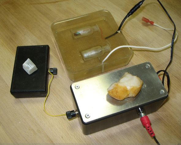 I put the board (which Sittingtaoist had kindly soldered together for me) into this little killer rad box (with the aluminum plate) I made. It has 100% STQ and other goodies packed in resin. I left only enough space for the circuit board on top of the epoxy, which is fine because it runs very cool day after day.
The black binding post on the larger box is for one ultrasound channel input. The witness plate is wired to the other input channel. There are 2 outputs going into the transmitter. So the plate is for one channel, and I plug something in for the other channel.
The red plug is for power, either my home solar system, a vehicle, or an old 14V adapter I had laying around.
Need for tuning. You will probably only need to do this once, but the K2572 has 2 trimmers that need to be tweaked with a tiny screwdriver. If these are not set to the optimum locations, you will not get good performance. It takes someone with energy sensitivity to adjust these.
For that matter, the K1803 also has a trimmer, as I mentioned earlier.
The K1803 mono pre-amps are still working fine for me. They seem to be fine for our purposes, too, but given that the stereo pre-amp is cheaper per channel (considering you don't need to buy an extra chip), uses 1/2 as much juice, and per Sittingtaoist is more stable, I won't be ordering any more K1803s.
 What is the use of having 2 inputs? Well, one could just be a printout of the golden ratio antenna, for example, to boost whatever the other trend is.
But what I generally do is have 2 different trends to a specific target. I kind of like putting each part of a 2-crystal Pitwexin-programmed set on its own input, as depicted above.
Sittingtaoist has purchased a tone generator kit, and we will be experimenting with running actual sound into the amp, at least one channel of it.
Of course, any channels used for sound will need to have both + and - signal input and output wires, and will not need a resistor.
Jan. 4, '08: Sittingtaoist told me that his measuring equipment had been faulty, and that the upper freq limit for the K1803 (when equipped with a NE5534 chip) is not 75 kHz, but 400 kHz.
Also, regarding the Oct. 19 entry on physical inputters, I wanted to mention that I recently realized that putting an inputter on or near the right hip is probably even more effective than a handheld one. And doesn't tie up your hand. One could wear something on a pouch on the hip, and have a wire going from it to a larger unit when driving. As well as a head-wire unit if desired.
Even any ordinary orgonite disk would work, though for greatest effectiveness it should have maximum STQ. Maximum receptiveness would be good, too.
Today I renamed this OTB, one reason being that I am getting more into regular audio amps as well, which I see has having different applications, like running signals directly into a mass of metal, even a mass of metal shavings in resin. I am having apparent insights into choosing particular amps and even modifying the circuits in some amps for better psionic use.
Experimenting is underway.
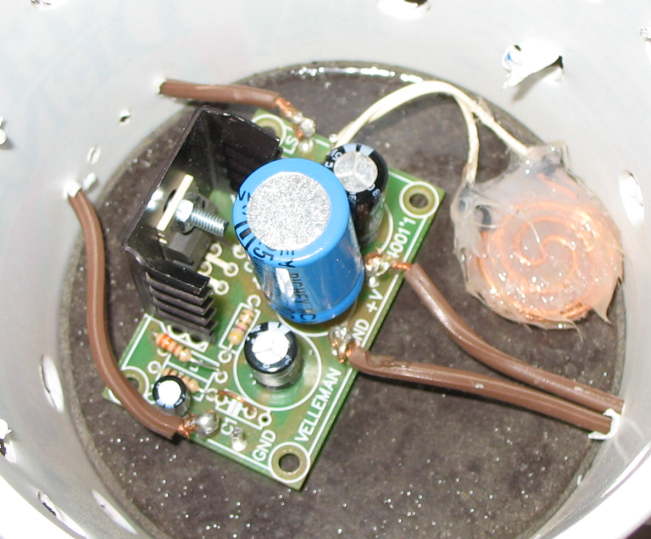
Mar. 24, '08: Good news. I have modified the Velleman K4001 amp (not a pre-amp) to make it into the best amp yet for psionic purposes. I haven't tested it real extensively, but some, and it seems stable. It works better than the pre-amps for the "ultrasound" bottle transmitters, however, it is even better for other applications. One could run a line from it to a bottle amp, then on from there to other things.
 I first showed this unit, sans modifications, on March 30 of last year in OTB 20. It was running way too hot, and eventually fried its central capacitor, but the reason for that turned out to be some wiring fault in my home solar setup. These amps run cool on a proper adapter or a 12V jump-start pack, or a healthy automotive system.
Here it is shown modified.
Here's what you gotta do if you want to rock 'n roll silently:
Ignore the GND posts for the signal input and ouput (left and right edges of board). Do not use them.
Replace the C1 capacitor (mine looked like a lentil) with a U-shaped piece of wire, like maybe the excess wire cut off a resistor or something.
Replace the R1 resistor with one of 330 ohms (Radio Shack has them).
Replace the central big capacitor, as shown, with a bigger one, specifically an electrolytic cap such as this one. Any 2200uF 25V electrolytic capacitor should do. I used a radial cap (both wires on one end), but if you do the following optional step, you could use an axial one (wire on each end) which would permit you to lay the cap down horizontally for a lower but wider profile.
If you are not going to do the last step, use a radial one, and follow the same polarity as for the original.
The central cap, according to Sittingtaoist, is the decoupling cap and the bigger one should just make it even smoother. It is not necessary to add additional decoupling caps to this unit.
It is questionable whether this last step is worthwhile. I think it only boosts effectiveness by 5%.
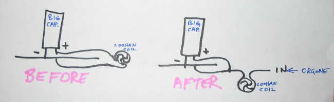
Make a Loohan coil in any size you want. It can be lenticular (as shown) or not. Just leave a way to attach a lead to each end.
This depicted coil is smothered in a glob of silicone seal to give it support against physical damage. Later I realized it is good to insert a piece of quartz or something into it first.
Insert this between the + lead from the biggest cap, and the hole where that + lead normally goes. You are not going to insert the + lead of the cap into the board. It will eventually find its way there via the coil loop.
I used a radial cap, and it is just supported on one side by the minus lead.
This coil is smothered in a glob of silicone seal to give it support against physical damage. Later I realized it is good to insert a piece of quartz or something into it first.
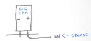 April 7, '08: Alrighty, a couple tips today regarding that amp. The + leg of the big cap is an ideal point to pump orgone into the system at from the side. It is unneccessary to make the coil. I suggest just leaving the + lead long after soldering it into its official proper place, as an input lead. I would not insert witnesses here, just clean energy of a non-electric kind.
 In the unlikely event that you did put in a Loohan coil, here's what you do. Cut the wire so that the coil is on the input wire. This is a good thing to have there.
OK, here's the second tip. This is particularly for use with sets-of-two stones as in OTB 27. This is where on the amp you want to input the companion stone for optimum mixing of signals.
In the spot where I told you to replace a capacitor with a piece of wire, instead of making a U shape, make like a big J. The bottom of the J connects the 2 empty holes underneath the the board, leaving a wire sticking up above. This is where you connect your wire from the companion stone. The primary stone is on the normal input.
If you have already installed a U, merely wrap the stripped end of some thin wire around the U and twist. No need to solder a non-electric connection; psionic energy ain't that particular.
You can just lay the stones on the wire ends, but for best results put each on a separate radionic device, even just a piece of resin with some hardware cloth in it. See today's entry in OTB 28. Two such devices, each with a wire connecting it to the amp,would work great.
Loohan
next OTB